


| Quantity: | |
|---|---|


| Item | Specification |
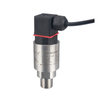
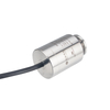
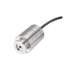
| Product Name | HPM18V Capacitance Diaphragm Gauge |
| Product Type | Capacitive Film Gauge (CDG) / Vacuum Gauge |
| Measuring Principle | Capacitor film principle |
| Sensor Element | Ceramic capacitive sensor |
| Measuring Range | 0.2 / 0.5 / 1 / 2 / 5 / 10 / 20 / 100 kPa |
| 2 / 5 / 10 / 20 / 50 / 100 / 200 / 1000 Torr | |
| 2 / 5 / 10 / 20 / 50 / 100 / 200 / 1000 mbar | |
| Output Signal / Supply | 4~20mA / Vs=10~30 VDC |
| 0~5VDC / Vs=8.5~30 VDC | |
| 0~10VDC / Vs=12~30 VDC | |
| RS485 / Vs=10~30 VDC | |
| Accuracy | ±0.1%FS (20kPa, 100kPa) |
| ±0.25%FS (5kPa, 10kPa) | |
| ±0.5%FS (500Pa, 1kPa, 2kPa) | |
| ±1.5%FS (200Pa) | |
| Long-term Stability | ±0.50%FS/year for ≤1kPa |
| ±0.25%FS/year for >1kPa | |
| Operating Temperature | -40~125°C |
| +125°C max. 120 min | |
| Ambient Temperature | -30~85°C |
| Storage Temperature | -30~85°C |
HPM18V is a capacitive vacuum gauge, also called a capacitive thin film vacuum gauge (CDG). This product uses a ceramic capacitive sensor as a sensitive element and directly measures pressure using a vacuum connection. Its analog output signals such as 0-5 or 0-10 VDC are proportional to the measured pressure and are not affected by the type and composition of the process gas. Ceramic has the characteristics of high elasticity, wear resistance, corrosion resistance, and fast heat dissipation, which makes the vacuum gauge have very good thermal stability and low temperature drift.
HPM18V capacitive vacuum gauge has high measurement accuracy, excellent overpressure resistance and excellent long-term stability. Its corrosion-resistant ceramic sensor is temperature compensated, has a wide operating temperature range, and has good zero-point stability. The vacuum gauge is compact in overall size, easy to use and reliable, and is suitable for accurate measurement of medium and low vacuum with complex gas composition.
Vacuum application
Laboratory and research and development
Semiconductor industry
Vacuum packaging
Plasma etching process equipment
Capacitor film principle
High precision and good stability
Has excellent anti-overload capability
Detection is not affected by gas type and composition
Fast response and small hysteresis
Direct pressure measurement, the analog output signal is proportional to the measured pressure
Support various pressure interfaces KF, CF, VCR, etc. in the vacuum industry
Getter
Vacuum chamber
Plate cable outlet
Breather tube
Sealing after exhaust
Fixed board
Detection diaphragm
Detection chamber
Detection hole
| Ordering Code | Part | Materials |
|---|---|---|
| S4 | Pressure Interface | SS304 |
| S6 | Pressure Interface | SS316L |
| PE | Pressure Interface | PEEK |
| M6 | Sensor | Ceramic Al2O3 99.9% |
| FK | O-Ring | FKM Fluoro rubber |
| NB | O-Ring | NBR Nitrile |
OD 1/2" Tube
OD 1/4" Tube
DN 16 ISO-KF
8 VCR, female thread
4 VCR, male thread & 8 VCR, male thread
4 VCR, female thread
M20X1.5
| Power supply+ (+V) | Power supply- (0V/+OUT) | Empty | |
|---|---|---|---|
| Hirschmann/DIN43650 | 1 | 2 | 3, 4 |
| Cable outlet | Red | Black | - |
| M12×1 | 1 | 2 | 3,4 |
| M12×1 (with cable) | Brown | Black | Blue, white |
| Power supply+(+V) | Common Ground (GND) | Output(+OUT) | Empty | |
|---|---|---|---|---|
| Hirschmann/DIN43650 | 1 | 2 | 3 | 4 |
| Cable outlet | Red | Black | Blue | - |
| M12×1 | 1 | 2 | 3 | 4 |
| M12×1(with cable) | Brown | Black | Blue | White |
| Power supply+(+V) | Power supply-(-V) | RS485A | RS485B | |
|---|---|---|---|---|
| Hirschmann/DIN43650 | 1 | 2 | 3 | 4 |
| Cable outlet | Red | Black | Yellow | Green |
| M12×1,4P | 1 | 2 | 3 | 4 |
| M12×1(with cable) | Brown | Black | Blue | White |
| Item | Specification |
| Product Name | HPM18V Capacitance Diaphragm Gauge |
| Product Type | Capacitive Film Gauge (CDG) / Vacuum Gauge |
| Measuring Principle | Capacitor film principle |
| Sensor Element | Ceramic capacitive sensor |
| Measuring Range | 0.2 / 0.5 / 1 / 2 / 5 / 10 / 20 / 100 kPa |
| 2 / 5 / 10 / 20 / 50 / 100 / 200 / 1000 Torr | |
| 2 / 5 / 10 / 20 / 50 / 100 / 200 / 1000 mbar | |
| Output Signal / Supply | 4~20mA / Vs=10~30 VDC |
| 0~5VDC / Vs=8.5~30 VDC | |
| 0~10VDC / Vs=12~30 VDC | |
| RS485 / Vs=10~30 VDC | |
| Accuracy | ±0.1%FS (20kPa, 100kPa) |
| ±0.25%FS (5kPa, 10kPa) | |
| ±0.5%FS (500Pa, 1kPa, 2kPa) | |
| ±1.5%FS (200Pa) | |
| Long-term Stability | ±0.50%FS/year for ≤1kPa |
| ±0.25%FS/year for >1kPa | |
| Operating Temperature | -40~125°C |
| +125°C max. 120 min | |
| Ambient Temperature | -30~85°C |
| Storage Temperature | -30~85°C |
HPM18V is a capacitive vacuum gauge, also called a capacitive thin film vacuum gauge (CDG). This product uses a ceramic capacitive sensor as a sensitive element and directly measures pressure using a vacuum connection. Its analog output signals such as 0-5 or 0-10 VDC are proportional to the measured pressure and are not affected by the type and composition of the process gas. Ceramic has the characteristics of high elasticity, wear resistance, corrosion resistance, and fast heat dissipation, which makes the vacuum gauge have very good thermal stability and low temperature drift.
HPM18V capacitive vacuum gauge has high measurement accuracy, excellent overpressure resistance and excellent long-term stability. Its corrosion-resistant ceramic sensor is temperature compensated, has a wide operating temperature range, and has good zero-point stability. The vacuum gauge is compact in overall size, easy to use and reliable, and is suitable for accurate measurement of medium and low vacuum with complex gas composition.
Vacuum application
Laboratory and research and development
Semiconductor industry
Vacuum packaging
Plasma etching process equipment
Capacitor film principle
High precision and good stability
Has excellent anti-overload capability
Detection is not affected by gas type and composition
Fast response and small hysteresis
Direct pressure measurement, the analog output signal is proportional to the measured pressure
Support various pressure interfaces KF, CF, VCR, etc. in the vacuum industry
Getter
Vacuum chamber
Plate cable outlet
Breather tube
Sealing after exhaust
Fixed board
Detection diaphragm
Detection chamber
Detection hole
| Ordering Code | Part | Materials |
|---|---|---|
| S4 | Pressure Interface | SS304 |
| S6 | Pressure Interface | SS316L |
| PE | Pressure Interface | PEEK |
| M6 | Sensor | Ceramic Al2O3 99.9% |
| FK | O-Ring | FKM Fluoro rubber |
| NB | O-Ring | NBR Nitrile |
OD 1/2" Tube
OD 1/4" Tube
DN 16 ISO-KF
8 VCR, female thread
4 VCR, male thread & 8 VCR, male thread
4 VCR, female thread
M20X1.5
| Power supply+ (+V) | Power supply- (0V/+OUT) | Empty | |
|---|---|---|---|
| Hirschmann/DIN43650 | 1 | 2 | 3, 4 |
| Cable outlet | Red | Black | - |
| M12×1 | 1 | 2 | 3,4 |
| M12×1 (with cable) | Brown | Black | Blue, white |
| Power supply+(+V) | Common Ground (GND) | Output(+OUT) | Empty | |
|---|---|---|---|---|
| Hirschmann/DIN43650 | 1 | 2 | 3 | 4 |
| Cable outlet | Red | Black | Blue | - |
| M12×1 | 1 | 2 | 3 | 4 |
| M12×1(with cable) | Brown | Black | Blue | White |
| Power supply+(+V) | Power supply-(-V) | RS485A | RS485B | |
|---|---|---|---|---|
| Hirschmann/DIN43650 | 1 | 2 | 3 | 4 |
| Cable outlet | Red | Black | Yellow | Green |
| M12×1,4P | 1 | 2 | 3 | 4 |
| M12×1(with cable) | Brown | Black | Blue | White |