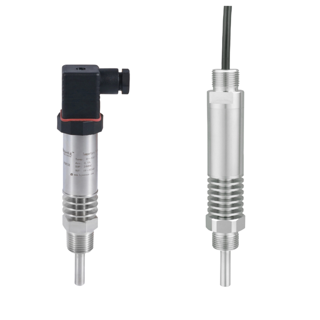
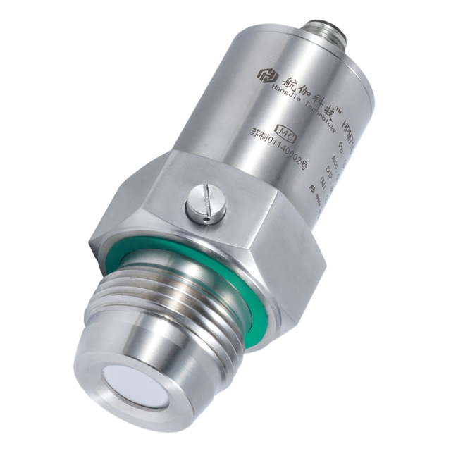
Flow Switch Working Principle And Mechanics Explained Simply
Views: 0 Author: Site Editor Publish Time: 2026-11-02 Origin: Site
How does a flow switch detect fluid movement and protect equipment? Its internal components convert flow changes into electrical signals. Different designs use magnetic, mechanical, or thermal sensing. This guide explains how they work, their key components, and practical industrial applications.
How Does a Flow Switch Work?
How Fluid Movement Activates a Flow Switch
A flow switch works by detecting fluid movement inside a pipeline. When liquid or gas enters its housing, the flowing medium creates force against an internal sensing element. This element may rotate, move, or respond to changes in heat transfer. Its movement depends on the switch design and operating conditions.
In a mechanical design, fluid force pushes a paddle or rotates an impeller. The movement changes the position of an internal magnet or mechanical contact. In a magnetic design, this movement changes the magnetic field near a sensing component. An electronic design may detect the same condition through a Hall sensor or thermal element. Once the detected condition reaches its switching threshold, the electrical output changes state.
The switching threshold is important because not every small movement should activate the device. Manufacturers design different flow ranges for different applications. A pump protection system may require a specific minimum flow condition. A water circulation system may need stable switching during normal operation. Therefore, buyers should match the activation and reset conditions to actual operating requirements.
How Internal Components Convert Flow Into Movement
Several internal components work together during operation. An impeller rotates when fluid passes through its blades. A paddle moves when flowing fluid applies force to its surface. A magnetic core transfers movement into a magnetic sensing area. Springs may provide resistance and help restore the original position.
These components do not perform identical functions. An impeller uses rotational movement, while a paddle usually responds through displacement. Magnetic components transfer movement without requiring direct electrical contact inside the fluid passage. This arrangement can help separate electrical sensing components from the wetted section.
The housing also influences performance. It guides fluid through the sensing chamber and supports the internal mechanism. Its material must suit the process medium, temperature, and pressure conditions. For example, reinforced nylon may suit certain water circulation applications. Metal constructions may be considered for other operating environments.
How Magnetic Sensing Triggers Electrical Signals
Magnetic sensing is common in compact flow switch designs. A permanent magnet moves or rotates as fluid passes through the sensing chamber. Its magnetic field then interacts with a nearby reed switch.
A reed switch contains two small metal contacts inside a sealed glass tube. When a suitable magnetic field approaches, the contacts attract and close. When the magnetic field moves away, they return to their original state. This process creates an electrical switching action without direct mechanical contact between the magnet and electrical contacts.
Hall-effect sensors use another approach. They detect changes in magnetic fields electronically. The sensor converts these changes into electrical signals. Depending on its circuit design, the output may be a voltage signal or pulse signal.
The two methods have different electrical characteristics. Reed switches provide contact-based switching. Hall-effect sensors provide electronic signal outputs. Buyers should check voltage requirements, output type, wiring, and controller compatibility before ordering.
How a Flow Switch Controls External Equipment
After detecting fluid movement, the flow switch sends an electrical signal to an external circuit. This circuit may connect to a pump, solenoid valve, controller, or alarm system. The switching action depends on the selected contact configuration.
Normally open contacts remain open under their defined normal condition. They close when the activation condition occurs. Normally closed contacts operate in the opposite way. They open when the specified switching condition is reached. Actual behavior depends on the product design and wiring arrangement.
For example, a circulation pump may operate only when sufficient fluid movement exists. If flow becomes too low, the switch changes its output state. A controller can then stop the pump or trigger an alarm. This arrangement helps reduce equipment risks caused by insufficient circulation.
Buyers can explore different configurations through the Flow Switch product range. Check the output type and electrical ratings before connecting any device to an external control system.
What Happens When Fluid Flow Stops?
When fluid movement decreases, the sensing element gradually returns toward its original position. A paddle may move back under spring force. A magnetic rotor may slow down or stop rotating. The magnetic field then changes around the sensing component.
In a reed switch design, the magnetic field may no longer hold the contacts closed. The contacts return to their original state. In a Hall-effect design, the electronic output changes according to the detected magnetic condition. The connected controller receives this change and responds according to its programmed logic.
The reset flow may differ from the activation flow. This difference is known as switching hysteresis. It helps prevent unstable switching when flow fluctuates near the operating threshold. Buyers should therefore confirm both activation and reset requirements.
How Flow Rate Influences Switching Behavior
Flow velocity directly affects the force applied to mechanical sensing elements. Higher velocity may produce stronger paddle movement or faster impeller rotation. Lower velocity may provide insufficient force to activate the mechanism.
However, the relationship depends on the internal design. Fluid density, viscosity, temperature, and passage dimensions can also influence switching behavior. A device designed for clean water may not perform identically in a viscous liquid. Solid particles may also interfere with moving components.
The minimum activation flow should match the actual process. Buyers should also check the reset threshold and acceptable flow fluctuations. These details help prevent missed signals and repeated switching.
Flow Switch Working Principle: Complete Operating Sequence
The complete operating process follows a clear sequence:
Fluid enters the flow switch housing.
Fluid movement creates force or changes heat transfer.
The paddle, impeller, or sensing element responds.
A magnetic or electronic sensor detects the change.
The electrical contact or output changes state.
The connected controller receives the signal.
The mechanism resets when flow conditions change.
This sequence explains how a flow switch converts fluid movement into an electrical control signal. Its main purpose is condition detection rather than continuous flow measurement.
Tip: A flow switch detects a switching condition. A flow meter measures and reports the actual flow rate.
What Are the Main Internal Components of a Flow Switch?

Flow Switch Housing and Fluid Passage
The housing forms the main structure of a flow switch. It guides fluid through the internal sensing chamber and protects important components. Its design also determines connection dimensions and installation requirements.
Common materials include plastic, nylon, brass, and stainless steel. Reinforced plastic can provide useful mechanical strength for suitable applications. Metal housings may offer different pressure and temperature capabilities. However, no material suits every fluid or operating environment.
The fluid passage must allow stable movement around the sensing element. Poor installation or unsuitable passage dimensions may affect switching performance. Buyers should check media compatibility, operating pressure, and connection standards before selecting a housing.
Impeller, Paddle, and Magnetic Core
The impeller, paddle, and magnetic core perform different mechanical functions. An impeller rotates when fluid moves across its blades. A paddle moves under fluid force. A magnetic core transfers movement into a magnetic field change.
Some compact flow switches combine a rotating impeller and magnetic core. The rotor turns as water passes through the chamber. Its magnetic field then activates a reed contact or Hall sensor. Other designs use a paddle connected to a mechanical switching structure.
The choice depends on the required flow threshold and application. Buyers should examine the internal construction rather than relying only on product names.
Reed Switch, Hall Sensor, and Electrical Contacts
The reed switch provides contact-based electrical switching. Its sealed contacts respond to a magnetic field. This structure supports simple switching circuits and compact designs.
A Hall sensor detects magnetic changes electronically. It can produce voltage or pulse outputs, depending on its circuit. These outputs may connect to controllers or monitoring systems. Electrical contacts also determine whether a product uses normally open or normally closed operation.
The output configuration must match the connected equipment. Incorrect voltage or current selection can cause unreliable operation or component damage.
Springs, Seals, and Reset Mechanisms
Springs help restore moving components after fluid force decreases. Their mechanical properties influence movement resistance and reset behavior. Seals prevent fluid from entering protected electrical areas. They also help maintain the integrity of the fluid passage.
Wear, contamination, and unsuitable operating conditions may affect these components. A damaged seal can cause leakage. A weakened spring may change switching behavior. Regular inspection helps identify problems before they affect connected equipment.
How Do Different Flow Switch Mechanisms Work?
Magnetic Reed Switch Mechanism
A magnetic reed flow switch uses a magnet and a reed contact. Fluid movement drives an internal rotor or magnetic component. As it moves, the magnetic field changes near the reed switch. The contacts then open or close.
This design is commonly used in water heaters and circulation systems. Its structure can support compact installation and simple electrical switching. The FS Normally Open Magnetic Reed Switch Piston Flow Switch is one example of this product category.
Its operation depends on magnet position, switching distance, and contact configuration. Buyers should also check the housing material and flow requirements.
Mechanical Paddle Flow Switch Mechanism
A mechanical paddle flow switch uses fluid force to move a paddle. The paddle connects to a mechanical switching structure. When fluid reaches the required condition, the paddle moves and activates the contact.
When flow decreases, a spring or another return mechanism restores the paddle. This movement changes the contact state. Paddle dimensions and spring resistance influence the switching threshold.
These devices are suitable for selected pipeline and HVAC applications. Buyers should confirm installation direction and paddle compatibility. They should also check whether the pipeline provides enough space for movement.
Hall-Effect Flow Switch Mechanism
A Hall-effect flow switch uses a magnetic element and electronic sensor. Fluid movement rotates an internal magnetic rotor. The Hall sensor detects changes in its magnetic field. The electronic circuit then generates an output signal.
Some designs produce voltage pulses during rotation. These signals can connect to electronic controllers. They may also support additional monitoring functions when the system allows it.
Unlike reed contacts, Hall sensors do not rely on mechanical contact closure. However, they require a suitable electrical supply and compatible signal processing. Buyers should confirm output voltage, wiring, and controller requirements.
Thermal Flow Switch Mechanism
A thermal flow switch detects changes in heat transfer. Its sensing element contains a heated component. When fluid moves across the sensor, it carries heat away from the sensing surface.
The electronic circuit detects the resulting temperature change. It then determines whether the flow condition meets the configured threshold. This method does not require a rotating impeller or moving paddle.
Thermal designs can monitor selected liquid and gas applications. Their suitability depends on fluid properties and operating temperatures. Buyers should verify the manufacturer's supported media and measurement conditions.
Comparison of Different Flow Switch Mechanisms
Mechanism | Main Component | Operating Principle | Typical Applications |
|---|---|---|---|
Magnetic reed | Magnet and reed contact | Magnetic contact activation | Water heaters, pumps |
Mechanical paddle | Paddle and micro-switch | Mechanical displacement | Water pipelines |
Hall-effect | Magnetic rotor and Hall sensor | Magnetic field detection | Water circulation |
Thermal | Heated sensing element | Heat transfer changes | Liquid and gas monitoring |
注释: Magnetic reed and Hall-effect designs use different electrical sensing methods. Their output requirements should be checked separately.
What Happens Inside a Flow Switch During Operation?
Fluid Entry and Internal Flow Movement
Fluid enters through the inlet and passes through the sensing chamber. The housing guides its movement around the internal components. Flow direction and velocity influence how the sensing element responds.
Some products require a specific installation direction. Incorrect positioning may affect the movement of internal components. Air pockets, turbulence, and contamination may also influence switching stability.
Mechanical Displacement or Rotor Rotation
As fluid moves, it creates force against the paddle or impeller. A paddle changes position, while an impeller rotates. The resulting movement depends on the fluid conditions and internal structure.
Mechanical resistance also affects the response. Springs, friction, and component dimensions influence activation. A suitable design should provide stable movement under normal operating conditions.
Magnetic Field Detection and Contact Switching
The moving magnet changes the magnetic field around the sensing component. A reed contact responds by opening or closing. A Hall sensor detects the magnetic change and generates an electronic output.
These signals represent the detected flow condition. They do not necessarily provide a continuous numerical flow value. That function belongs to a flow meter or another measurement instrument.
Signal Transmission and Equipment Response
The electrical output travels to a controller or connected circuit. The controller evaluates the signal according to its control logic. It may activate a pump, stop equipment, open a valve, or trigger an alarm.
For example, an industrial circulation system may require a minimum flow condition. If the switch detects insufficient flow, the controller can initiate a protective response. This helps reduce the risk of operating equipment under unsuitable conditions.
Where Are Flow Switches Used in Industrial Applications?

Air Conditioning and HVAC Systems
HVAC systems use flow switches to monitor water circulation. They can help confirm whether cooling or heating water moves through the required pipeline. A switching signal may protect chillers and circulation equipment.
Magnetic and electronic designs can serve different HVAC configurations. Buyers should consider fluid temperature, pressure, flow threshold, and installation direction.
Water Heaters and Domestic Water Systems
Water heaters often require adequate water movement during operation. A flow switch can detect incoming water or circulation conditions. Its output may control heating activation or pump operation.
If the flow condition falls below the required threshold, the control system can respond. This helps prevent operation under unsuitable water circulation conditions.
Industrial Pumps and Water Circulation Systems
Industrial pumps rely on suitable fluid circulation. A flow switch can detect insufficient flow or unexpected interruptions. Its signal can support pump control and equipment protection.
Water treatment systems also use flow detection in selected process stages. Buyers should check fluid cleanliness and material compatibility. These factors influence long-term switching reliability.
Solenoid Valves and Automated Equipment
Flow switches can connect to solenoid valves and automated control systems. They provide signals based on detected flow conditions. A controller can then adjust valve operation or trigger an interlock.
This arrangement supports automatic process control. However, the switch itself does not replace a complete safety system. Its electrical ratings and control logic must suit the application.
What Factors Affect Flow Switch Working Performance?
Minimum Flow Rate and Switching Threshold
The minimum activation flow determines when a switch changes state. The reset threshold determines when it returns. These values may differ because of mechanical resistance and switching hysteresis.
A switch with an unsuitable threshold may activate too late. It may also produce unstable signals during changing flow conditions. Buyers should request activation and reset specifications before ordering.
Fluid Properties and Operating Conditions
Fluid density and viscosity affect mechanical movement. Temperature may influence seals and housing materials. Corrosive substances may also damage unsuitable wetted components.
Impurities can block narrow passages or interfere with moving parts. Buyers should identify the actual medium before selecting a product. They should also confirm pressure and temperature limits.
Installation Direction and Pipeline Conditions
Installation direction affects different flow switch mechanisms. Some products support vertical installation only. Others allow different mounting positions. The manufacturer's instructions should determine the final arrangement.
Flow direction must also match the marked direction on the housing. Nearby elbows and valves may create turbulence. Adequate installation space helps maintain reliable operation.
Common Flow Switch Problems and Troubleshooting
Unstable switching may result from several causes. A stuck paddle can prevent normal movement. A blocked passage may restrict fluid flow. Damaged magnets or sensors may also interrupt signal generation.
Electrical problems require separate inspection. Incorrect wiring, loose connections, or unsuitable voltage can prevent normal switching. Buyers should inspect the fluid passage, mechanical components, and electrical circuit systematically.
A practical troubleshooting sequence includes:
Check whether fluid reaches the device.
Inspect the pipeline for blockage.
Verify installation direction.
Examine the paddle or impeller movement.
Check magnetic sensing components.
Test electrical connections and output signals.
Compare actual conditions against product specifications.
Tip: Always isolate electrical power and depressurize the pipeline before internal inspection.
Conclusion
A flow switch converts fluid movement into electrical signals. Its mechanism depends on sensing technology and internal components. Proper installation ensures reliable operation and equipment protection. HJSensor offers magnetic reed and thermal flow switches. Its product range supports different sensing and output requirements. These solutions help buyers improve fluid monitoring and control.
Q: How does a flow switch work?
A: It detects fluid movement and triggers electrical switching.
Q: What activates a magnetic flow switch?
A: A moving magnet activates reed contacts or sensors.
Q: What is the difference between reed and Hall sensors?
A: Reed sensors switch contacts. Hall sensors generate electronic signals.
Q: Why does a flow switch fail to activate?
A: Low flow, blocked passages, or damaged components may cause failure.
Q: Where are flow switches commonly used?
A: They monitor HVAC systems, water heaters, pumps, and pipelines.