How to Connect a 4–20mA Transmitter to a PID Controller
Views: 0 Author: Site Editor Publish Time: 2026-09-22 Origin: Site
Industrial automation relies heavily on precise analog signals. Incorrectly wiring a 4–20mA process signal can result in dead loops, erratic process control, or damaged I/O modules. These failures ultimately lead to expensive operational downtime. Engineers must understand how components interact to keep systems online. Connecting a transmitter to a PID (Proportional-Integral-Derivative) controller requires matching the transmitter’s power configuration with the controller’s analog input capabilities. You will often encounter 2-wire, 3-wire, or 4-wire setups in the field. Each demands a specific wiring approach. We designed this guide to provide a technically sound, step-by-step framework. You will learn how to establish, scale, and troubleshoot a reliable loop. We also outline hardware evaluation criteria for engineers and technicians. By following these steps, you ensure optimal signal integrity across your industrial control networks.
Key Takeaways
Identify the Power Source: The most critical step is determining whether the PID controller, the transmitter, or an external power supply provides the 24VDC excitation.
Match Wire Configurations: 2-wire (loop-powered) systems are industry standard for their simplicity, while 4-wire setups are necessary for high-draw devices.
Verify Loop Scaling: Physical wiring must be paired with accurate software scaling (mapping 4mA to the process zero-point and 20mA to the full-scale value) within the PID parameters.
Prioritize Isolation: Specifying hardware with isolated inputs prevents ground loops, the leading cause of signal drift in industrial environments.
Assessing Your Hardware: Sourcing vs. Sinking the Current Loop
Every successful control system begins with a thorough hardware assessment. A standard 4–20mA loop requires three vital components. You need a stable power supply. You need a transmitter to regulate the current. Finally, you need a receiver to interpret the signal. The PID controller normally acts as this receiver. Understanding how these elements share power dictates your entire wiring strategy. We must categorize devices as either "sourcing" (providing power) or "sinking" (receiving power).
Controller Capabilities (The Receiver)
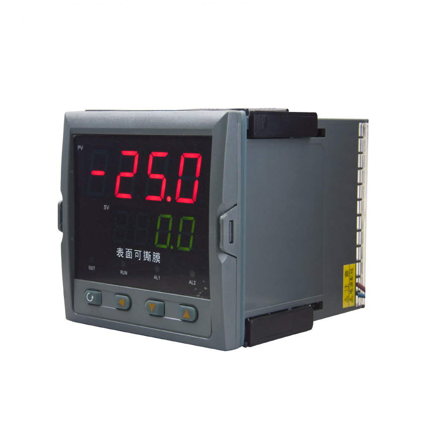
First, inspect your receiver module. You must check if the PID temperature controller features a built-in 24VDC loop power supply. A controller with internal power acts as a sourcing device. It sends voltage out to the sensor. Conversely, many basic controllers only act as passive receivers. They sink the current but do not provide excitation voltage.
This creates a crucial decision point. If your controller lacks internal excitation, you cannot simply connect a passive sensor. You must procure an external DIN-rail power supply. Failing to verify this detail causes frustrating "dead loop" scenarios during commissioning.
Transmitter Configurations (The Sensor)
Transmitters come in three primary configurations. You must identify your sensor type before stripping any wires.
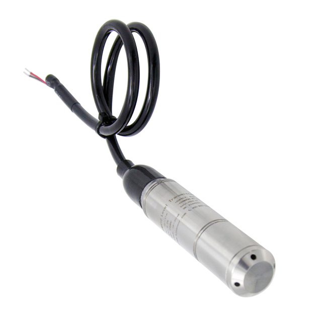
2-Wire Transmitters (Loop-Powered): This design draws power and transmits the signal over the exact same two wires. It operates flawlessly for most low-power devices. You will typically see this on a standard 4-20mA temperature transmitter or pressure sensor.
3-Wire Transmitters: These devices use a shared ground for both power and the signal return. They are less common today. Engineers often avoid them because they remain highly prone to voltage drop issues over long distances.
4-Wire Transmitters (Self-Powered): High-draw devices require this setup. They need dedicated power wires (e.g., 110VAC or 24VDC) completely separate from the two analog signal wires. Magnetic flow meters and gas analyzers frequently use 4-wire configurations.
Hardware Configuration Comparison Chart
Configuration Type | Power Source Location | Wire Count | Common Applications | Advantage |
|---|---|---|---|---|
2-Wire (Loop-Powered) | Provided by Loop (Controller or External) | 2 Wires | Temperature, Pressure sensors | Simple wiring, highly reliable |
3-Wire | Dedicated Power Pin, Shared Ground | 3 Wires | Legacy proximity sensors | Cost-effective for short runs |
4-Wire (Self-Powered) | Independent Local Power Supply | 4 Wires | Flow meters, Motor drives | Supports high power consumption |
Executing 4-20mA Current Loop Wiring (Step-by-Step)
Implementation reality demands strict safety protocols. Always de-energize the system completely before terminating any wires. Transient voltage spikes can easily blow a controller’s internal fuse. Worse, they can permanently damage the analog-to-digital converter. Safety ensures reliable startups.
Wiring a 2-Wire Transmitter (Controller Powered)
This scenario assumes your PID controller provides the 24VDC excitation. It represents the cleanest and most common installation method.
Step 1: Locate the positive (+) 24VDC excitation terminal on your PID. Connect a wire from this terminal directly to the positive (+) terminal of your transmitter.
Step 2: Connect a wire to the negative (-) terminal of the transmitter. Route this wire back to the positive (+) analog input (AI) terminal on the PID.
Step 3: You must close the circuit. Jumper or connect the negative (-) analog input terminal on the PID back to the controller's internal power supply common/ground.
Best Practice: Always double-check terminal designations in the manufacturer manual. Abbreviations vary wildly between brands.
Wiring with an External Power Supply
When the controller lacks internal power, you must introduce an external 24VDC unit. This changes the wiring path. You must wire all three devices in a strict series circuit.
Route a wire from the External Power Supply (+) to the Transmitter (+).
Route a wire from the Transmitter (-) to the PID Analog Input (+).
Route a wire from the PID Analog Input (-) back to the External Power Supply (-).
Adhering to strict standards for 4-20mA current loop wiring prevents future headaches. Maintain shielded twisted-pair cabling throughout the entire run. Ground the drain wire (shield) at one end only. Terminating the shield at both ends creates a ground loop antenna. This pulls electromagnetic interference directly into your process signal.
Configuring and Scaling the PID Controller Parameters
Physical wiring represents only half the battle. The physical loop remains completely meaningless without correct software scaling. Your PID must translate the raw analog current into a readable Process Variable (PV). If you skip this phase, the controller cannot execute accurate math.
Input Type Selection
Controllers often feature universal inputs. They can accept volts, milliamps, or direct thermocouple signals. You must ensure the controller's physical dip switches align with your software settings. Set both to "Current" (4-20mA). Never leave them set to "Voltage" (0-10V) or "Thermocouple." Feeding 24VDC through an input configured for a delicate thermocouple will destroy the module instantly.
Scaling the Range (Math & Logic)
You map the electrical signal to real-world engineering units through two main parameters.
Low Scale (4mA): This defines the absolute minimum process value. If your pressure transducer reads 0 to 100 PSI, assign 4mA to equal 0 PSI. For a freezer monitor, 4mA might represent -50°C.
High Scale (20mA): This corresponds to your maximum process value. Using the previous examples, 20mA equals 100 PSI or 150°C. The controller extrapolates all values perfectly in between.
Sensor Break Logic: Current loops offer a massive safety advantage called a "live zero." 0mA indicates a physical failure, not a zero reading. Configure the controller behavior for signals falling below 3.8mA. This condition should trigger an immediate alarm. It must safely shut down the control output to prevent process runaways.
Common Mistake: Forgetting to match the controller’s high scale to the transmitter’s calibrated range. If the sensor maxes out at 500°C but the PID expects 1000°C, every reading will display exactly half of reality.
Hardware Evaluation Criteria: Choosing the Right Components
Engineers constantly face upgrade cycles. When replacing or upgrading loop components, you need a solid decision-stage framework. Evaluate new hardware based strictly on reliability and integration ease. Do not rely solely on familiar brand names.
Galvanic Isolation
Always evaluate if the PID analog inputs isolate themselves from the main power supply and the digital outputs. Galvanic isolation acts as an invisible firewall for electricity. Non-isolated inputs remain highly vulnerable. They require expensive external signal isolators to function safely in noisy plants. Spending slightly more on an isolated controller saves hours of troubleshooting later.
Input Impedance (Burden Voltage)
Every device in a series loop resists the current slightly. This resistance creates a voltage drop. You must ensure the total loop resistance does not exceed the transmitter’s maximum drive capability. Calculate the total wire resistance plus the PID internal resistor (usually 250 ohms). A standard 24VDC supply pushes through about 600 to 1000 ohms effortlessly. If you daisy-chain multiple displays, you might hit this limit. Exceeding it causes the signal to artificially cap out below 20mA.
Form Factor and Modularity
Assess your future expansion needs. Determine whether the controller supports plug-and-play I/O cards. Fixed-input controllers work perfectly for standalone machines. However, scalable production lines benefit from modular bases. You can slide a new analog input card into a modular rack in seconds. This prevents you from ripping out the entire brain of the machine just to add one sensor.
Troubleshooting Common Implementation Failures
Even perfect designs encounter reality. Experience-based diagnostics separate average technicians from great ones. You must logically trace a fault when the PID controller reads a system error or an inaccurate process variable. Never guess. Measure everything systematically.
The 0mA / Open Loop Error
A reading of 0mA means electricity has stopped flowing entirely. The controller will likely flash a "Sensor Break" or "Open Loop" alarm.
Causes: You might have a broken wire in a conduit. You might have blown the controller's internal fuse. Someone may have wired the loop with reversed polarity.
The Fix: Grab your digital multimeter (DMM). Set it to measure DC current (mA). Break the loop at any terminal block. Place your meter probes in series with the circuit. If your meter reads 4-20mA but the controller reads zero, the controller input is dead. If the meter reads 0mA, check your power supply voltage first. Next, verify polarity.
The 250-Ohm Resistor Trick
Sometimes you inherit legacy hardware. Many older controllers only accept 1-5VDC voltage inputs. They lack a dedicated 4-20mA setting. You do not need to throw them away. You can use a simple 250-ohm precision resistor. Place this resistor directly across the positive and negative analog input terminals. Ohm's Law explains the magic: Voltage = Current x Resistance (V = I x R). A 4mA signal (0.004 Amps) multiplied by 250 ohms equals 1 Volt. A 20mA signal (0.020 Amps) equals 5 Volts. The controller perfectly reads the current loop as a 1-5VDC signal.
Signal Drift / Ground Loops
Ground loops act like parasitic ghosts in industrial systems. They occur when a circuit finds multiple paths to ground. Different grounding points sit at slightly different voltage potentials. This forces stray current through your signal shield.
You will identify ground loops by their symptoms. Your temperature readings will slowly drift up and down for no reason. Measurements will look erratic or noisy. The solution requires verifying single-point grounding. Disconnect the shield wire from the sensor end. Leave it connected only at the controller cabinet panel ground. If issues persist, install a dedicated din-rail signal isolator. This physically breaks the electrical continuity while passing the data magnetically or optically.
Conclusion
Connecting a 4–20mA transmitter to a PID controller dictates the overall stability of your automated process. Mastering these wiring configurations prevents catastrophic system failures. You protect valuable assets by respecting voltage limits and isolation barriers. Always verify component documentation for specific terminal designations. Ensure proper loop architecture before applying power. Determine if a 2-wire or 4-wire setup fits your specific load. Finally, perform a low/high current simulation test using a loop calibrator. Testing signals prior to engaging live process control guarantees a safe, accurate, and highly responsive automation environment.
FAQ
Q: Can I connect multiple PID controllers to a single 4-20mA transmitter?
A: Yes, you can achieve this by wiring the analog inputs of the controllers in series. However, you must calculate the total loop resistance. Ensure the combined input impedance does not exceed the transmitter's driving capacity. Excessive voltage drop will corrupt the high-end readings.
Q: What happens if I wire the 4-20mA loop backward (reverse polarity)?
A: Most modern industrial transmitters feature built-in reverse polarity protection. They simply will not power on. No smoke will appear, but the loop will read exactly 0mA at the controller. Flipping the wires back to the correct orientation usually restores normal operation instantly.
Q: Why use 4-20mA instead of 0-10V for a temperature transmitter?
A: Current loops remain highly immune to ambient electrical noise. They do not suffer from signal degradation over long cable runs like voltage drops do. Additionally, they provide a "live zero" at 4mA. This instantly flags a broken wire or dead sensor when the signal drops to 0mA.