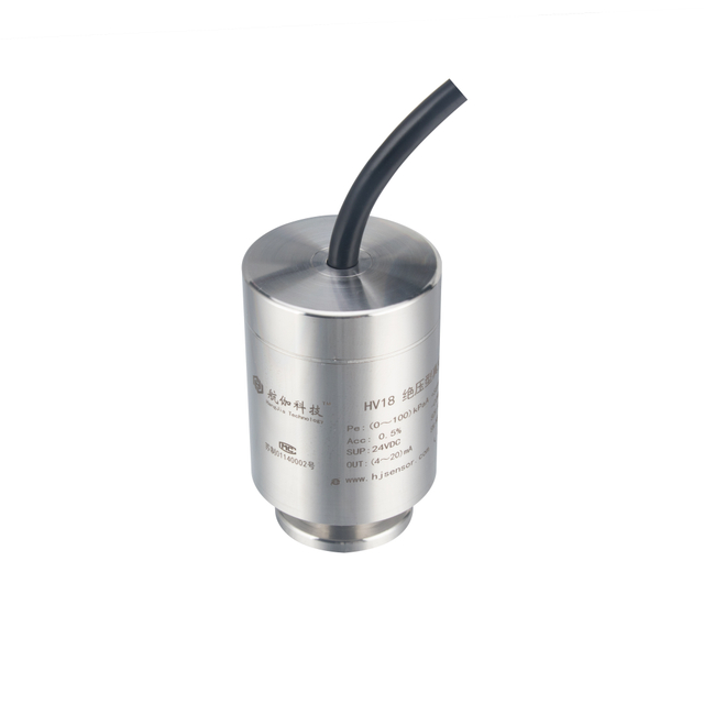
HVAC Refrigerant Pressure Transmitter vs Air Differential Pressure Transmitter
Views: 0 Author: Site Editor Publish Time: 2026-08-18 Origin: Site
Although both are used in HVAC systems, HVAC refrigerant and air differential pressure transmitters measure different variables and cannot be interchanged. A refrigerant pressure transmitter normally measures gauge pressure at one point in a sealed refrigerant circuit. An air differential pressure transmitter compares two air pressures, such as the upstream and downstream sides of a filter. The first typically works in bar ranges with a threaded process connection; the second often works in Pa or low-kPa ranges with two tubing ports. Selecting by the word “HVAC” alone can result in overrange, leakage, media damage, or a signal that is useless to the controller. The correct choice starts with the pressure reference, medium, expected range, process connection, output signal, and the exact point being monitored.

Key Takeaways
A refrigerant transmitter measures pressure at one point relative to its reference, while an air differential transmitter measures the difference between two air points.
Refrigerant circuits commonly require bar-range measurement and a pressure-tight threaded fitting. Ducts, filters, and rooms usually require Pa or low-kPa differential measurement and two air tubes.
A single-port refrigerant transmitter cannot directly measure pressure drop across a filter. A clean-air differential transmitter must not be exposed to refrigerant or liquid.
HPM135B is intended for refrigeration pressure measurement with a 0–1…50 bar range and 0.5–4.5 V output. HPM310 and HPM311 are designed for low differential pressure in dry, clean, non-corrosive gas.
Output selection must match the controller input, supply voltage, cable length, grounding arrangement, and required diagnostics.
Choose the transmitter from the application conditions, not from the general label “HVAC pressure sensor.”
Quick Comparison
The following table shows why these two transmitter types belong to different parts of an HVAC system.
Selection Point | Refrigerant Pressure Transmitter | Air Differential Pressure Transmitter |
|---|---|---|
Measured variable | Pressure at one point in a refrigerant circuit | Pressure difference between two air points |
Pressure reference | Usually gauge pressure relative to atmosphere | Differential pressure: P-high minus P-low |
Number of pressure ports | One process pressure port | Two ports: high and low |
Medium | Refrigerant circuit medium, subject to verified compatibility | Dry, clean, non-corrosive gas; not liquid |
Typical range | Bar-range pressure | Pa or low-kPa differential pressure; wider ranges may also be available |
Process connection | Pressure-tight threaded fitting | Low-pressure tubing or hose connection |
Output | Commonly voltage for compact OEM refrigeration controls; model dependent | 4–20 mA, voltage, or RS485 depending on model |
Typical application | Compressor suction/discharge, chiller, heat pump, freezer, ice machine | AHU filter, duct pressure, fan status, cleanroom or room pressure |
Recommended HJSensor model | HPM135B | HPM310 or HPM311 |
The central question is not which design is more accurate. It is whether the transmitter is built for the measured medium, pressure magnitude, reference type, connection, and controller.
What Is an HVAC Refrigerant Pressure Transmitter?
An HVAC refrigerant pressure transmitter converts refrigerant-line pressure into an electrical signal for monitoring, protection, or control. It is normally installed directly at a pressure tap, valve body, manifold, or short pressure line. Because the refrigerant circuit is sealed and pressurized, the connection must be compatible with the equipment and capable of maintaining a leak-tight seal.
Gauge Pressure Measurement in Refrigerant Circuits
Most refrigeration control points are concerned with pressure relative to surrounding atmospheric pressure. A gauge-pressure transmitter has one process port and uses atmospheric pressure as its reference. If the process port is open to atmosphere, the gauge reading should be near zero.
This differs fundamentally from differential measurement. A single-port refrigeration pressure transmitter reports the pressure at its installation point. It does not know the pressure at another location unless a second transmitter is installed and the controller calculates the difference. Even then, subtracting two bar-range gauge transmitters is usually a poor substitute for a purpose-built low-air differential transmitter when the desired result is only a few hundred pascals.
Compressor Suction and Discharge Pressure
Suction and discharge are two common monitoring points, but they operate at different pressures and serve different control purposes. Suction pressure can support evaporating-condition monitoring, capacity control, and low-pressure protection. Discharge pressure can support condensing-condition monitoring and high-pressure protection.
The transmitter range should cover normal operation plus credible startup and transient conditions without becoming so wide that useful resolution is lost. The suction-side and discharge-side transmitters may therefore require different ranges even on the same refrigeration system. A technician should also verify whether the application can enter vacuum, because a 0-bar lower limit cannot represent negative gauge pressure.
Pressure measurement alone does not confirm refrigerant charge or diagnose every system fault. Temperature, refrigerant type, operating mode, compressor state, and equipment-specific control logic must be considered together.
Condensation Resistance and Refrigerant Compatibility
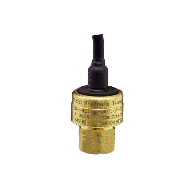
Refrigeration equipment can expose a sensor and connector to condensation, temperature cycling, and vibration. The HPM135B uses a compact brass housing and an anti-condensation design for refrigeration service. Its listed working-temperature range is −35 to 110°C, but installation conditions must still protect the electrical connection and cable routing from standing water, mechanical strain, and unsuitable enclosure conditions.
“Refrigeration use” does not mean automatic compatibility with every refrigerant, lubricant, sealant, or cleaning chemical. Before specifying a refrigerant pressure sensor, confirm the exact refrigerant, wetted materials, seal materials, maximum temperature, pressure range, overload requirement, and thread standard. This is especially important when replacing a sensor in equipment designed for a different refrigerant or pressure class.
HPM135B Application Examples
The HPM135B has a listed measuring range of 0–1…50 bar, ±1.0% FS accuracy, two-times-full-scale overload, and a three-wire 0.5–4.5 VDC output. Available process connections include NPT1/4, G1/4, and 7/16-20UNF male or female options; electrical connection choices include a Packard connector or cable outlet.
These characteristics suit compact refrigeration equipment where a voltage-input controller needs a direct pressure signal. Application examples include:
Water-cooled chillers and screw compressor units
Ground-source and air-source heat pumps
Commercial freezers and refrigerated cabinets
Ice machines
Refrigeration units requiring pressure monitoring or protective control input
For a chiller pressure transmitter, the range must be chosen for the actual suction or discharge point. Do not assume that one 0–50 bar version is the best choice for every point merely because it covers the maximum family range.
What Is an Air Differential Pressure Transmitter?
An air differential pressure transmitter measures the difference between two gas pressures and converts that difference into a controller signal. The high-side port and low-side port are connected to separate pressure taps. The output represents P-high minus P-low, not either pressure by itself.
Measuring the Difference Between Two Air Points
Consider an AHU filter. One tube connects to the duct upstream of the filter and the other connects downstream. A clean filter creates a relatively small pressure drop. As dust accumulates, resistance increases and the differential pressure rises. The transmitter can send that trend to a building automation system or trigger an alarm at an established limit.
The same principle applies to room pressure. Connecting the high port to a positively controlled room and the low port to a corridor allows the transmitter to show whether the required pressure relationship is maintained. Reversing the tubes reverses the sign, which is why port identification matters during installation.
Low-Pressure Pa and kPa Ranges
Ventilation measurements are often much smaller than refrigerant-line pressures. A duct pressure transmitter may need to resolve tens or hundreds of pascals, while a refrigerant transmitter may be working across several or dozens of bar. One bar equals 100 kPa, or 100,000 Pa, which shows the size of the mismatch.
Range selection should place the expected operating value within a useful portion of the span while preserving enough margin for abnormal conditions. A 0–100 kPa air DP range may survive a large differential, but it would be poorly matched to a filter that normally changes by only a few hundred pascals. Conversely, a 0–200 Pa transmitter can be over-ranged by pressure surges if it is connected carelessly.
Duct, Filter, and Room Pressure Applications
Air differential transmitters are commonly used for:
Pressure drop across AHU filters
Supply, return, or exhaust duct static-pressure comparison
Fan operation or airflow-proving logic
Cleanroom pressure relative to an adjacent room or corridor
Stairwell, isolation-room, or laboratory pressure monitoring
Boiler air supply and underground ventilation
For these uses, the measured medium must match the product limitation. HPM310 and HPM311 are specified for dry, clean, non-corrosive gas and cannot measure liquids. If the air stream contains water droplets, oil mist, aggressive vapor, heavy dust, or condensate, use suitable separation, filtration, purge arrangements, or a transmitter designed for that medium.
HPM310 vs HPM311
Both models measure micro differential pressure in clean gas, but their configuration differs.
Feature | HPM310 | HPM311 |
Measurement | Low gas differential pressure | Low gas differential pressure |
Listed range family | From 0–100 Pa to 0–100 kPa, with bidirectional ranges available | From 0–200 Pa to 0–100 kPa, with negative/bidirectional configurations listed |
Pressure connection | Ø8 mm barbed nozzle | Dual air-pressure connections |
Output | 4–20 mA, voltage, or RS485 | 4–20 mA or voltage |
Local operation | Manual zero function | LED or LCD display, field range setting, and PV reset |
Housing/installation emphasis | Compact duct and ventilation measurement | Sealed aluminum-alloy housing with local display and configuration |
Choose HPM310 when a compact air pressure difference sensor with RS485 or several analog-output options is needed. HPM311 is more suitable when local indication and field configuration are important. The exact range determines the available accuracy, so the range code should be checked rather than applying one accuracy value to the entire family.
Seven Key Differences
1. Gauge Pressure vs Differential Pressure
The refrigerant transmitter normally measures pressure relative to atmosphere. The air DP transmitter compares its two connected pressure points. This reference difference determines the sensor architecture and how the reading should be interpreted.
2. Single Port vs Dual Port
A refrigerant transmitter has one process pressure connection. An air differential transmitter has a high port and a low port. Leaving one DP port open can create a gauge-like low-pressure measurement, but only when the datasheet and application permit that arrangement.
3. Refrigerant vs Dry Air
The refrigerant transmitter is built for direct process contact subject to verified compatibility. HPM310 and HPM311 are for dry, clean, non-corrosive gas. Their air ports and sensing path must not be exposed to refrigerant or liquid.
4. Bar Range vs Pa/kPa Range
Refrigerant circuits use much higher pressures than typical air systems. Installing a low-range air transmitter on a refrigerant line would cause severe overrange. Installing a wide bar-range sensor across an HVAC filter would produce little useful resolution.
5. Threaded Process Fitting vs Hose Connection
Refrigerant service requires a pressure-tight threaded fitting selected for the equipment connection and sealing method. Air DP transmitters normally connect to pressure taps through flexible tubing. The tube material, diameter, routing, and tap location all affect the measurement.
6. Voltage Output vs BAS-Compatible Output
The HPM135B uses 0.5–4.5 VDC output for compact equipment controls. Air transmitters may offer 4–20 mA, voltage, or RS485 for BAS integration. “BAS-compatible” still requires matching the exact input type, scaling, supply, wiring, and communication protocol.
7. Refrigeration Equipment vs Ventilation System
Refrigerant transmitters support compressor, chiller, heat-pump, freezer, and ice-machine pressure monitoring. Air DP transmitters support filters, fans, ducts, rooms, and airflow-related controls. The application location usually reveals the correct transmitter type before accuracy is considered.
Why These Transmitters Cannot Be Interchanged
Using the wrong device is not simply a matter of obtaining a less accurate reading. It can create mechanical, electrical, and control-system failures.
Overrange: Refrigerant pressure can exceed a low-air sensor range by several orders of magnitude, permanently shifting or rupturing the sensing element.
Media damage: Refrigerant, compressor oil, or liquid can attack or contaminate a sensor designed only for clean gas.
Leakage: A hose barb and plastic tube are not substitutes for a refrigeration-rated threaded connection and approved sealing method.
Incorrect readings: A single-port gauge transmitter cannot directly measure the pressure difference between two air points. A wide range also hides small duct-pressure changes.
Poor control response: Incorrect range or scaling may make the controller respond too slowly, oscillate, or fail to detect a real change.
Unsafe system operation: A wrong pressure signal can interfere with protection and control logic. Safety devices required by the equipment design must not be replaced by an unsuitable general-purpose transmitter.
Nanjing Hangjia Electronic Technology Co., Ltd. (HIGHJOIN) separates refrigerant-pressure and clean-air-differential models because their sensing conditions are fundamentally different. The ordering specification should preserve that separation even when both devices report to the same HVAC controller.
HVAC Refrigerant vs Air Differential Pressure Transmitters: Which Should You Use?
Use the measured point—not the equipment name—as the starting point for HVAC transmitter selection.
HVAC Application | What Must Be Measured? | Suitable Transmitter Type | Practical Model Direction |
Compressor suction | Refrigerant-line pressure at the suction point | Refrigerant gauge-pressure transmitter | HPM135B with a range suited to normal, transient, and possible vacuum conditions |
Compressor discharge | Higher refrigerant-line pressure | Refrigerant gauge-pressure transmitter | HPM135B with appropriate high-side range and connection |
Chiller | Suction or discharge refrigerant pressure | Refrigerant pressure transmitter | HPM135B; select separately for each monitored point |
Heat pump | Refrigerant circuit pressure in heating and cooling modes | Refrigerant pressure transmitter | HPM135B after checking full operating envelope |
Refrigerant pressure protection | A pressure input for approved equipment control/protection logic | Compatible refrigerant pressure transmitter | Match range, output, connector, and equipment requirements; retain required safety controls |
AHU filter | Pressure drop across the filter | Air differential pressure transmitter | HPM310 or HPM311 in a low range suited to the filter limit |
Ventilation duct | Duct pressure relative to another point or atmosphere | Air differential pressure transmitter | HPM310 for compact multi-output measurement; HPM311 where display is helpful |
Fan monitoring | Pressure rise or airflow-proving differential | Air differential pressure transmitter | HPM310 or HPM311 with suitable response and range |
Cleanroom pressure | Room-to-corridor or room-to-room pressure difference | Air differential pressure transmitter | HPM311 where local display and field configuration are required |
An HVAC pressure sensor request should therefore include more than the equipment name. State the pressure reference, medium, minimum and maximum operating pressure, allowable overpressure, temperature, process connection, electrical connector, supply, output, cable length, mounting location, and controller input.
Output Signal and Controller Compatibility
The sensor and controller must use the same signal type and scaling. A mechanically correct transmitter with an incompatible output cannot provide a usable measurement.
Output | Main Characteristics | Common HVAC Use | Points to Confirm |
0.5–4.5 V | Live-zero voltage output; compact three-wire connection | OEM refrigeration equipment and embedded controllers | Supply voltage, common ground, input range, scaling, cable length |
0–5 V | Simple voltage input | Local equipment and short cable runs | Ground offset, electrical noise, input impedance, scaling |
0–10 V | Widely accepted by many building controllers | Dampers, fans, room and duct controls | Controller input type, shared common, voltage drop and noise |
4–20 mA | Live zero and good tolerance of voltage drop over longer loops | BAS, PLC, and industrial HVAC panels | Loop supply, input resistance, two-/three-wire arrangement, fault interpretation |
RS485 | Digital, addressable, and suitable for multi-device networks | Distributed monitoring and BAS integration | Protocol, baud rate, parity, addressing, termination, register map |
The HPM135B’s 0.5–4.5 VDC signal fits controllers designed for that input. HPM310 supports 4–20 mA, voltage, or RS485; HPM311 supports 4–20 mA or voltage. Do not assume that RS485 automatically means Modbus compatibility unless the ordered model documentation specifies the protocol.
An HVAC differential pressure transmitter connected to a BAS is often specified with 4–20 mA or 0–10 V, but the better option depends on the installed wiring and controller. Current loops are generally preferred for longer cable routes and electrically noisy plant areas. Voltage signals are convenient when the controller already provides the correct supply and the cable run is controlled. RS485 is useful when digital networking and multiple addressed devices justify the added configuration work.
Installation Differences
Refrigerant and air DP transmitters require different installation procedures because one opens into a pressurized refrigerant circuit and the other connects through low-pressure air tubing.
For a refrigerant transmitter:
Confirm refrigerant, maximum pressure, temperature, thread, sealing method, and electrical connector.
Isolate and depressurize the circuit according to the equipment procedure before installation or replacement.
Use the specified seal and tightening method. Avoid applying torque through the housing or electrical connector.
Position and support the transmitter and cable to limit vibration, connector strain, and trapped water.
Leak-test the completed connection using the approved method for the refrigerant system.
Verify the controller’s 0.5–4.5 V scaling at known pressure conditions before returning equipment to service.
For an air differential transmitter:
Select pressure taps that represent the intended upstream/downstream or room/reference conditions.
Mount the transmitter in the orientation allowed by its instructions and where zero checks remain accessible.
Connect the higher-pressure point to H and the lower-pressure point to L. Label both tubes.
Keep tubing runs short, supported, unkinked, and protected from heat, sharp edges, water traps, and accidental disconnection.
Equalize both ports and perform the permitted zero adjustment before applying the differential pressure.
Check the sign and scaling at the BAS. A negative reading often indicates reversed tubes or a reversed pressure relationship, not a failed sensor.
Moisture is a particular concern in air tubing. Condensate can block a tube, add a liquid-head error, or reach a sensor that cannot measure liquids. Tap design and tube routing should prevent water from collecting in the pressure path.
Conclusion
HVAC refrigerant and air differential pressure transmitters solve different measurement problems. A refrigerant transmitter such as HPM135B measures one-point gauge pressure in a sealed refrigerant circuit, using a threaded connection, a bar-range span, and a 0.5–4.5 V output. An air differential transmitter such as HPM310 or HPM311 compares two clean-air points, normally through tubing, across Pa or low-kPa ranges with controller-oriented analog or digital outputs.
The two devices should never be selected by the word “HVAC” alone. Identify the medium, pressure reference, number of ports, minimum and maximum pressure, overpressure, process connection, output, and application point first. This prevents overrange and leakage, preserves useful measurement resolution, and gives the controller a signal it can interpret correctly.
FAQs
Can a refrigerant pressure transmitter measure duct air pressure?
It can measure relatively high gauge air pressure if the medium and range are compatible, but it is generally unsuitable for low HVAC duct differential pressure. Its single port cannot directly compare two duct points, and a bar-range span usually provides poor resolution for a Pa-level signal.
Can an air differential pressure transmitter contact refrigerant?
No, not when it is specified only for dry, clean, non-corrosive gas. HPM310 and HPM311 cannot measure liquids and should not be connected to a refrigerant circuit. Refrigerant pressure, oil, and chemical exposure can damage the sensing path and create leakage or unsafe operation.
Why do refrigerant transmitters use higher pressure ranges?
Compressors create substantial suction and discharge pressures to circulate refrigerant and support evaporation and condensation. These operating pressures are far above the small pressure differences used to monitor filters, ducts, fans, or rooms, so refrigerant transmitters commonly use bar ranges rather than Pa ranges.
Which output signal is better for a building automation system?
There is no universal best signal. A 4–20 mA loop is robust over longer cables, 0–10 V is convenient for many BAS inputs, and RS485 supports addressable digital networking. Use the signal supported by the controller and verify power, scaling, wiring, protocol, and fault handling.
Which transmitter should be used for an HVAC filter?
Use a low-range air differential pressure transmitter connected across the filter. HPM310 or HPM311 can be selected according to the required span, output, display, and field-configuration needs. The alarm limit should be based on the filter and AHU design rather than a generic value.
Can the same controller accept both transmitter types?
Yes, if it has compatible input channels and each channel can be scaled separately. For example, one channel may accept the HPM135B’s 0.5–4.5 V signal while another accepts a 4–20 mA air DP signal. The controller does not make the sensors interchangeable; it only receives their different measurements.