Temperature Transmitter Explained | Connection and Calibration
Views: 0 Author: Site Editor Publish Time: 2026-04-17 Origin: Site
Ever wonder how industries keep precise temperature control? Temperature transmitters play a crucial role in this process. They convert sensor signals into standardized outputs for accurate monitoring.
In this post, you’ll learn what temperature transmitters are, their role in control systems, common output signals, and compatible sensors.
Temperature Transmitter Explained: Connection and Calibration
Types of Temperature Transmitter Connections: 2-Wire vs 4-Wire
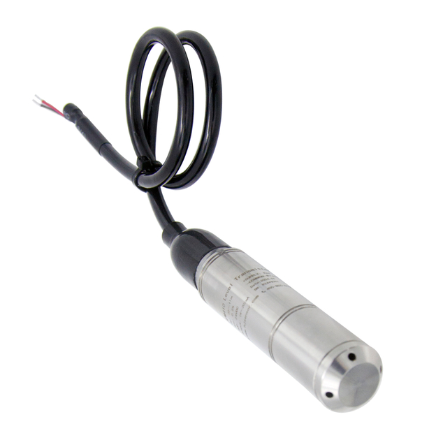
Temperature transmitters typically come in two main wiring configurations: 2-wire and 4-wire. A 2-wire transmitter uses the same pair of wires to supply power and transmit the output signal, usually a 4-20mA current loop. This setup simplifies wiring and reduces costs but may limit signal quality over long distances. In contrast, a 4-wire transmitter has separate pairs for power supply and signal output, offering better isolation and improved accuracy, especially in noisy industrial environments.
Integrating Temperature Transmitters into Control Loops
In process control systems, temperature transmitters connect temperature sensors to controllers like PLCs or DCS. The transmitter converts sensor signals into standardized outputs, commonly 4-20mA or 0-10V, which the controller reads to monitor or adjust process variables. Proper integration requires attention to wiring, grounding, and shielding to minimize signal interference. Additionally, selecting the right transmitter type—such as an RTD transmitter or thermocouple transmitter—ensures compatibility with the sensor and control system.
Common Temperature Sensors: Thermocouples and RTDs
Two primary sensors pair with temperature transmitters: thermocouples and Resistance Temperature Detectors (RTDs). Thermocouples generate a small voltage proportional to temperature changes, making them suitable for wide temperature ranges and rapid response. RTDs vary resistance with temperature and offer higher accuracy and stability, often with 2, 3, or 4-wire configurations to reduce lead wire effects. Many temperature transmitters support both sensor types, facilitating flexible applications.
Smart and Digital Temperature Transmitters with HART Protocol
Modern temperature transmitters often feature smart capabilities using digital communication protocols like HART. These transmitters provide standard analog output (e.g., 4-20mA) plus digital data such as sensor diagnostics, calibration info, and device status. HART-enabled transmitters allow remote configuration and calibration, improving maintenance efficiency and reducing downtime. They also support integration into advanced control systems, enhancing process reliability.
Step-by-Step Calibration Process for Temperature Transmitters
Calibrating a temperature transmitter ensures its output accurately reflects the measured temperature. The general process includes:
Isolate the transmitter from the process to prevent interference.
Connect a signal simulator or calibrator to mimic sensor output (millivolts for thermocouples, resistance for RTDs).
Apply known reference values across the temperature range.
Measure the transmitter output (4-20mA or 0-10V) at each point.
Adjust zero and span settings to align output with reference values.
Repeat measurements to verify accuracy.
Document calibration results for quality control.
Tools for Calibration: Signal Reference Calibrators and Decade Boxes
Calibration tools vary depending on the sensor type and transmitter design. For RTD transmitters, decade resistance boxes simulate precise resistance values corresponding to temperatures. For thermocouple transmitters, signal reference calibrators generate small millivolt signals mimicking thermocouple outputs. Modern multifunction calibrators can simulate both sensor types and measure transmitter outputs, streamlining the calibration process.
Comparison of Old Style vs New Style Calibration Methods
Older temperature transmitters use manual adjustments via multi-turn potentiometers labeled Zero and Span. Technicians physically turn these to fine-tune output current at low and high calibration points. Newer transmitters often lack manual pots and instead rely on software-based calibration using communication tools like HART communicators or USB interfaces. This digital calibration offers greater precision, easier repeatability, and remote access, improving overall maintenance efficiency.
Tip: When calibrating temperature transmitters, always simulate sensor signals accurately using proper tools like signal reference calibrators or decade boxes to ensure precise and reliable calibration results.
Understanding Temperature Transmitter Calibration
Why Calibration is Critical for Accuracy and Safety
Calibration of a temperature transmitter is essential to ensure that the device accurately reflects the true temperature measured by the sensor. Over time, factors like environmental conditions, aging components, and mechanical stresses can cause drift in transmitter output. Without regular calibration, inaccurate temperature readings may lead to poor process control, safety hazards, and compromised product quality. For example, in pharmaceutical manufacturing, even slight temperature deviations can affect product efficacy, making precise calibration vital.
Calibration Procedures and Best Practices
The calibration process typically involves comparing the transmitter’s output to known reference temperatures and making necessary adjustments. Here’s a standard procedure for calibrating temperature transmitters:
Isolate the transmitter from the process to avoid interference.
Simulate sensor signals using a calibrator or decade resistance box, depending on whether it’s a thermocouple transmitter or RTD transmitter.
Apply reference values across the temperature range, such as 0%, 25%, 50%, 75%, and 100% of the span.
Measure the transmitter output (commonly 4-20mA or 0-10V) at each point.
Adjust zero and span settings to align output with reference inputs.
Repeat measurements to confirm accuracy.
Document results for quality control and compliance.
Using proper tools and following manufacturer guidelines enhances calibration reliability.
Using HART Communicators for Digital Calibration
Modern smart temperature transmitters often support digital calibration via HART (Highway Addressable Remote Transducer) communicators. This tool connects to the transmitter loop and allows technicians to:
View and modify calibration settings remotely.
Enter precise reference temperatures.
Digitally adjust zero and span values.
Retrieve diagnostic data for troubleshooting.
HART-enabled calibration reduces manual errors, saves time, and supports remote maintenance, especially for temperature transmitters with display or integrated digital interfaces.
Calibration Ranges and Their Importance
Each temperature transmitter has a specified calibration range, defining the minimum and maximum temperatures it can accurately measure. Calibration must cover this entire range to ensure linearity and proper scaling of the output signal, such as the standard 4-20mA current loop. For example, a transmitter calibrated from -50°C to 150°C must be tested at multiple points within this range. Operating outside the calibrated range can cause measurement errors and affect process control.
Impact of Sensor Calibration on Transmitter Accuracy
The accuracy of a temperature transmitter heavily depends on the sensor it works with, such as an RTD transmitter or thermocouple transmitter. If the sensor itself is out of calibration, the transmitter’s output will be inaccurate regardless of its own calibration status. Therefore, calibrating temperature sensors and transmitters together ensures overall measurement precision. Regular sensor checks and replacements, combined with transmitter calibration, maintain optimal system performance.
Tip: Always calibrate temperature transmitters using the same sensor type and configuration installed in the field to ensure the accuracy and reliability of your temperature measurement system.
Types of Temperature Sensors Compatible with Transmitters
Thermocouples: Characteristics and Signal Output
Thermocouples are widely used temperature sensors compatible with many temperature transmitters. They consist of two dissimilar metal wires joined at one end, producing a small voltage that changes with temperature. This voltage, typically in the millivolt range, is proportional to the temperature difference between the measurement junction and the reference (cold) junction. Thermocouple transmitters convert this millivolt signal into a standard output, such as 4-20mA or 0-10V, suitable for control systems.
Thermocouples are favored for their:
Wide temperature range (from -200°C to over 1800°C, depending on type)
Fast response time
Simple construction with only two wires
However, they require cold junction compensation to correct for the reference junction temperature, which temperature transmitters often handle internally.
Resistance Temperature Detectors (RTDs): Lead Configurations and Response
RTDs measure temperature by correlating it to the electrical resistance of a metal, commonly platinum. The resistance increases predictably as temperature rises, allowing precise temperature measurement. RTD transmitters convert this resistance change into standard signals like 4-20mA.
RTDs come with different lead configurations:
2-wire RTD: Simplest but susceptible to lead wire resistance errors.
3-wire RTD: Common industrial choice; compensates for lead resistance.
4-wire RTD: Most accurate; eliminates lead resistance effects entirely.
RTDs provide excellent accuracy and stability but have a narrower temperature range compared to thermocouples (typically -200°C to 850°C). They are ideal for applications requiring precise temperature control.
Infrared Sensors and Other Sensor Types
Beyond thermocouples and RTDs, some temperature transmitters support other sensor types:
Infrared (IR) sensors: Measure temperature without contact by detecting thermal radiation. Useful for moving or hazardous targets.
Thermistors: Semiconductor devices with high sensitivity, often for limited temperature ranges.
Integrated sensor-transmitter units: Combine sensor and transmitter in one housing for compact installations.
While less common, these sensors expand the versatility of temperature transmitter applications.
Selecting the Right Sensor for Your Application
Choosing the correct temperature sensor transmitter combination depends on:
Temperature range: Thermocouples cover extreme temperatures; RTDs suit moderate ranges.
Accuracy requirements: RTDs generally offer higher accuracy and stability.
Response time: Thermocouples respond faster.
Environmental conditions: Harsh environments might favor rugged thermocouples.
Signal compatibility: Ensure the temperature transmitter supports the sensor type and output, such as temperature transmitter 4 20mA or temperature transmitter 0 10V.
Installation constraints: Lead wire length and wiring method (2-wire, 3-wire, 4-wire) affect measurement accuracy.
For example, an rtd transmitter 4 20mA is ideal for precise temperature measurement in pharmaceutical processing, while a thermocouple transmitter may be better for high-temperature furnaces.
Tip: Always verify that your temperature transmitter is compatible with the sensor type and wiring configuration to ensure accurate temperature sensor 4 20mA output and reliable process control.
Temperature Transmitter Installation and Connection Best Practices
Proper Wiring Techniques for 2-Wire and 4-Wire Transmitters
Correct wiring is crucial for reliable temperature transmitter performance. For 2-wire temperature transmitters, the same pair of wires provides power and carries the 4-20mA signal. This wiring reduces installation complexity and cost but requires careful attention to wire length and quality to avoid voltage drops that affect accuracy.
In contrast, 4-wire transmitters use separate pairs for power and signal output. This separation improves signal integrity, especially in electrically noisy industrial environments. When connecting an RTD transmitter 4 20mA or a thermocouple transmitter, ensure that the wiring matches the sensor type and transmitter specifications. For RTDs, use the correct lead configuration (2, 3, or 4-wire) to minimize lead resistance errors. Always follow manufacturer wiring diagrams to avoid miswiring.
Shielding and Grounding to Minimize Signal Interference
Industrial environments often have electromagnetic interference (EMI) from motors, drives, and other equipment. To maintain a clean temperature sensor 4 20mA output, use shielded cables for the transmitter connection. Ground the cable shield at one end only to prevent ground loops that can introduce noise.
Proper grounding of the temperature transmitter housing and sensor junction boxes also helps reduce interference. When installing a temperature transmitter with display in the field, ensure all metallic parts are grounded according to local electrical codes. Avoid running signal cables parallel to high-power cables to minimize inductive coupling.
Cold Junction Compensation: Why and How It’s Done
Thermocouple transmitters require cold junction compensation because the thermocouple voltage depends on the temperature difference between the measurement junction and the reference (cold) junction. Since the cold junction temperature varies with the environment, the transmitter must measure it and compensate to provide accurate temperature readings.
Most modern thermocouple transmitters include built-in cold junction compensation circuits. They use internal temperature sensors near the terminal block to measure the cold junction temperature and adjust the output accordingly. When connecting a thermocouple transmitter, verify that the cold junction compensation is enabled and functioning properly to avoid measurement errors.
Field Mounting vs DIN Rail Mounting Considerations
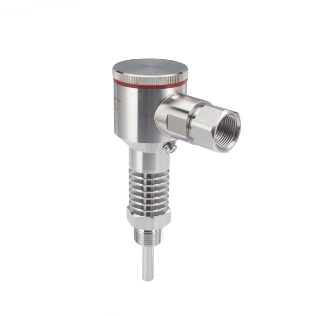
Temperature transmitters come in various packages, including field-mounted units and DIN rail-mounted modules. Field-mounted transmitters are installed close to the sensor, often in harsh environments. They reduce signal degradation over long cable runs and simplify wiring by integrating sensor and transmitter in one assembly.
DIN rail-mounted transmitters are typically installed in control panels or enclosures. They offer easier access for maintenance and calibration but may require longer sensor wiring. When choosing between these types, consider factors like ambient conditions, ease of access, and wiring complexity. For example, an RTD transmitter with display mounted on a DIN rail allows quick status checks, while a field-mounted transmitter minimizes wiring issues on remote sensors.
Tip: Always use shielded, properly grounded cables and follow manufacturer wiring guidelines to ensure accurate temperature transmitter connection and minimize signal interference in your control system.
Advancements in Temperature Transmitters
Wireless Temperature Transmitters and Their Benefits
Wireless temperature transmitters have revolutionized temperature measurement by eliminating the need for extensive wiring. These devices transmit temperature sensor signals via wireless protocols such as Wi-Fi, Bluetooth, or proprietary radio frequencies. This reduces installation costs and complexity, especially in large or hard-to-access industrial sites.
Key benefits include:
Flexibility: They can be installed in remote or hazardous locations without running cables.
Reduced Maintenance: Fewer physical connections mean less wear and tear.
Easy Integration: Wireless transmitters can quickly connect to existing control systems or cloud platforms.
Real-Time Monitoring: Data can be accessed instantly from any location, improving process oversight.
Wireless temperature transmitters often support standard outputs like 4-20mA via gateways, ensuring compatibility with PLCs and DCS.
Integration with Modern Control Systems (PLC, DCS)
Modern temperature transmitters, including RTD transmitters and thermocouple transmitters, are designed for seamless integration with control systems such as Programmable Logic Controllers (PLCs) and Distributed Control Systems (DCS). They provide reliable temperature sensor 4 20mA output or 0-10V signals that controllers use to maintain process variables.
Advanced transmitters support digital communication protocols, enabling:
Remote configuration and diagnostics
Improved data accuracy
Simplified wiring and troubleshooting
This integration enhances process control, reduces downtime, and optimizes system performance.
Digital Communication Protocols: FOUNDATION FIELDBUS and PROFIBUS
Beyond analog outputs, many temperature transmitters now incorporate digital communication standards like FOUNDATION FIELDBUS and PROFIBUS. These protocols support multi-drop wiring and allow multiple devices to share a single communication bus.
Advantages include:
Enhanced data exchange: Transmitters send detailed diagnostics, calibration data, and sensor status.
Reduced wiring complexity: Fewer cables lower installation costs.
Improved scalability: Easy to add or replace devices without rewiring.
For example, a temperature transmitter with display can show live values locally while communicating detailed data over PROFIBUS to the control system.
Future Trends in Temperature Measurement Technology
Temperature transmitter technology continues to evolve, focusing on:
Increased smart capabilities: More transmitters will feature embedded diagnostics, predictive maintenance alerts, and self-calibration functions.
Wireless mesh networks: These offer robust, scalable communication for large industrial plants.
Integration with IoT: Transmitters will connect directly to cloud platforms for advanced analytics and remote monitoring.
Miniaturization and ruggedization: Smaller, more durable transmitters will suit harsh environments and compact installations.
Energy harvesting: Future wireless transmitters may use ambient energy sources, reducing battery dependence.
These trends aim to improve accuracy, reliability, and ease of use for temperature sensor transmitters across industries.
Tip: When upgrading to advanced temperature transmitters, consider compatibility with your existing control system and communication protocols to maximize integration benefits and future-proof your installation.
Troubleshooting and Maintaining Temperature Transmitters
Common Causes of Inaccurate Temperature Readings
Inaccurate temperature readings from a temperature transmitter can stem from several issues. One common cause is sensor degradation or damage, where the RTD or thermocouple sensor no longer produces correct signals. Wiring problems such as loose connections, broken wires, or incorrect temperature transmitter connection also disrupt signal transmission. Electrical interference from nearby equipment can introduce noise, affecting the temperature sensor 4 20mA output signal quality. Additionally, cold junction compensation errors in thermocouple transmitters lead to incorrect temperature calculations. Environmental factors like extreme humidity, vibration, or temperature cycling may also cause transmitter drift over time.
Regular Maintenance and Calibration Intervals
To maintain accuracy and reliability, it’s essential to perform regular maintenance and calibrating temperature transmitters on a scheduled basis. Most industrial standards recommend calibration every six months, but this can vary depending on the application’s criticality and environmental conditions. During maintenance, inspect wiring integrity, check for corrosion, and verify that shielding and grounding remain effective. Recalibrate the transmitter using appropriate tools like signal reference calibrators or HART communicators to ensure the output aligns with actual temperature values. Keeping a calibration log helps track performance trends and anticipate maintenance needs.
Identifying and Resolving Signal Attenuation and Noise
Signal attenuation and noise can degrade the quality of the temperature transmitter 4 20mA or 0-10V output. To identify these issues, use a multimeter or loop calibrator to measure signal strength at various points along the wiring. If attenuation occurs, check for long cable runs or poor-quality wiring causing voltage drops. Noise often arises from electromagnetic interference (EMI); shielding cables with grounded metal braid and separating signal cables from power lines reduces this problem. If interference persists, consider using a 4-wire transmitter configuration or installing signal isolators. Proper grounding of the temperature transmitter with RTD or thermocouple sensors is crucial to minimize noise.
Ensuring Long-Term Reliability and Performance
Long-term reliability of temperature transmitters depends on a combination of proper installation, regular calibration, and preventive maintenance. Use high-quality temperature sensor transmitters matched to the process requirements, such as an RTD transmitter 4 20mA for precise control or a robust thermocouple transmitter for high temperatures. Protect transmitters from harsh environmental conditions by selecting suitable enclosures or field-mounted units. Employ digital temperature transmitters with HART protocol for remote diagnostics and easier troubleshooting. Regularly update firmware when available and replace sensors showing signs of wear. These practices help maintain consistent temperature transmitter working and accurate process control over time.
Tip: Schedule regular calibration and maintenance checks for your temperature transmitters to quickly detect and fix wiring issues, sensor faults, and signal noise, ensuring accurate and reliable temperature measurement.
Conclusion
Maximizing accuracy and efficiency with temperature transmitters requires proper connection and calibration. Correct installation and regular calibration ensure reliable temperature readings and process control. Choosing the right transmitter, such as 2-wire or 4-wire models, suits specific sensor types and environments. Accurate temperature measurement supports consistent process performance and safety. HIGHJOIN offers advanced temperature transmitters that combine smart features with robust design, providing precise control and easy integration for diverse industrial applications. Trust HIGHJOIN to enhance your temperature measurement systems.
FAQs
Q: What is a temperature transmitter and how does it work?
A: A temperature transmitter converts signals from temperature sensors like RTDs or thermocouples into standardized outputs such as 4-20mA or 0-10V. It ensures accurate temperature sensor output for control systems by compensating for sensor characteristics and environmental factors.
Q: How do I connect a temperature transmitter properly?
A: Proper temperature transmitter connection depends on the wiring type—2-wire or 4-wire. Use shielded cables, follow sensor lead configurations (e.g., RTD 3-wire or 4-wire), and ensure correct grounding to minimize noise and maintain accurate temperature sensor 4 20mA output.
Q: Why is calibrating temperature transmitters important?
A: Calibrating temperature transmitters aligns their output with known reference temperatures, ensuring accurate process control and safety. Regular calibration prevents drift caused by aging or environmental factors, maintaining reliable temperature transmitter working and measurement precision.
Q: What tools are used for temperature transmitter calibration?
A: Calibration typically uses signal reference calibrators for thermocouple transmitters and decade resistance boxes for RTD transmitters. Modern smart temperature transmitters may also be calibrated digitally via HART communicators for precise zero and span adjustments.
Q: What are the differences between RTD transmitters and thermocouple transmitters?
A: RTD transmitters measure resistance changes for high accuracy and stability, often using 3 or 4-wire connections. Thermocouple transmitters convert small voltage signals over wide temperature ranges and require cold junction compensation. Both provide outputs like temperature transmitter 4 20mA for control systems.
Q: How can I troubleshoot inaccurate readings from a temperature transmitter?
A: Check for sensor damage, wiring faults, improper grounding, and cold junction compensation errors. Use a multimeter to verify signal integrity and ensure temperature transmitter connection follows manufacturer guidelines. Regular calibration also helps maintain accurate temperature sensor transmitter output.