Pressure Transmitter Installation & Maintenance: A Complete Guide for Industrial Reliability
Views: 0 Author: Site Editor Publish Time: 2026-04-11 Origin: Site
Pressure Transmitter Installation & Maintenance: A Complete Guide for Industrial Reliability
In modern industrial automation, pressure transmitters are the silent guardians of process safety and efficiency. Whether in oil & gas, chemical processing, water treatment, or power generation, these instruments convert physical pressure into precise electrical signals (4-20mA, HART, etc.) that drive control systems.
However, industry data suggests that over 60% of pressure transmitter failures are not due to manufacturing defects, but rather improper installation or lack of maintenance. This guide details the best practices for installing and maintaining pressure transmitters to ensure long-term stability, while highlighting the specific product features that solve common field challenges.
Part 1: Pre-Installation & Selection Strategy
Before picking up a wrench, the right foundation must be laid. Selecting a transmitter that matches the specific process environment is the first step toward reliability.
1. Understanding the Environment
Media Compatibility: Is the medium corrosive (acid/alkali)? If so, a standard 316L stainless steel diaphragm might fail. You need a transmitter with a Hastelloy C or Ceramic diaphragm to resist corrosion.
Temperature: High temperatures (>100°C) can damage the sensor electronics. A remote seal or cooling fin design is often necessary.
Hazardous Areas: If installing in Zone 1 or Div 1 areas, the device must carry ATEX or IECEx certification.
2. Featured Product Spotlight: The Industrial Workhorse
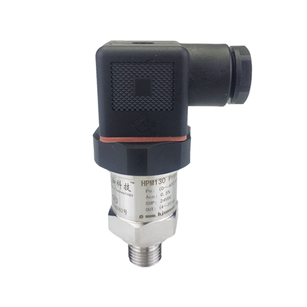
For general industrial applications requiring robustness and versatility, we recommend the HPM180 General Pressure Transmitter.
Product Highlight:
Wide measuring range, can measure gauge pressure, absolute pressure and sealed gauge pressure
Universal for oil, water and gas
Multiple pressure interfaces available
Multiple output signals available
Wide temperature range compensation, small temperature drift
Good long-term stability
Part 2: Step-by-Step Mechanical Installation
The physical installation determines the accuracy of the measurement. Improper mounting can introduce stress, leading to "zero drift" or permanent damage.
1. Choosing the Pressure Tap Point
The location where you tap into the pipe is critical.
For Gas Measurement: The tap should be on the top or side of the pipe. This prevents condensate (liquid) from collecting in the impulse lines and affecting the reading.
For Liquid Measurement: The tap should be on the side or bottom (0-45° angle). This prevents gas bubbles from getting trapped in the line.
For Steam: Always use a siphon (pigtail loop). This creates a water seal that prevents hot steam from directly hitting the sensitive sensor diaphragm.
2. Mounting Orientation
Vibration: Avoid mounting directly on vibrating pipes. Use a separate stand or bracket to isolate the transmitter.
Accessibility: Ensure the display (if equipped) is readable and the junction box is accessible for wiring.
Drainage: Install the transmitter slightly below the tap point for liquid service to allow for self-draining.
3. Sealing and Torque
Use appropriate sealants (PTFE tape or anaerobic sealant) on threads, but ensure no sealant enters the pressure port.
Caution: Do not overtighten. Excessive torque on the process connection can deform the sensor housing and cause calibration shifts.
Part 3: Electrical Installation & Signal Integrity
A perfect mechanical install can be ruined by poor wiring. Electrical noise is the enemy of precision.
1. Wiring Best Practices
Cable Selection: Use shielded twisted-pair cables. The shielding acts as a Faraday cage, protecting the low-voltage signal from electromagnetic interference (EMI) generated by motors or VFDs.
Grounding: Ground the shield at the control system end (single-point grounding) to avoid ground loops.
Conduit Seals: In outdoor or washdown environments, use conduit seals to prevent water from wicking down the cable and entering the transmitter housing (the "chimney effect").
2. Power Supply
Ensure the power supply is stable (typically 24V DC). Voltage drops over long cable runs can affect performance. Most modern transmitters have reverse polarity protection, but it is best to double-check connections (+ to +, - to -).
Part 4: Specialized Applications & Product Showcase
Different industries have unique pain points. Here is how to address them with specific installation techniques and products.
Scenario A: The Sanitary Challenge (Food & Pharma)
In food and beverage or pharmaceutical industries, hygiene is paramount. Bacteria can grow in dead spaces (crevices) within the piping.
Installation: Use "flush mount" or "diaphragm seal" transmitters. The sensor membrane sits flush with the pipe wall, allowing for full drainage and cleaning (CIP/SIP).
Material: Must be polished 316L stainless steel (Ra < 0.8µm).
Product Spotlight: HPM710 Flat Diahragm Pressure Transmitter

Scenario B: The Clogging Challenge (Wastewater & Slurry)
Measuring pressure in sewage or slurry is difficult because solids can clog the small impulse lines.
Solution: Use a transmitter with a large, open pressure port or a sensor which is highly resistant to abrasion and clogging.
Product Spotlight: HPM410-C

Part 5: Commissioning & Calibration
Once installed, the transmitter must be configured.
1. Zero Trim
Even with perfect installation, the hydrostatic head (the height of the liquid in the impulse line) can create a slight offset.
Action: Vent the pressure to atmosphere (or equalize for differential pressure) and perform a "Zero Trim" via the local buttons or a HART communicator.
2. Range Setting
Ensure the Lower Range Value (LRV) and Upper Range Value (URV) match the process requirements. For example, setting 0 to 10 bar corresponds to 4mA and 20mA respectively.
Part 6: Routine Maintenance Schedule
To maximize the lifecycle of your investment, adhere to a strict maintenance schedule.
Frequency | Maintenance Task | Critical Check |
Weekly | Visual Inspection | Check for leaks at flanges/threads. Verify display is active. |
Monthly | Impulse Line Check | Blow down (purge) impulse lines to remove sediment or moisture. |
Annually | Calibration | Verify accuracy against a certified reference standard (5-point check). |
Annually | Electrical Check | Inspect cable insulation and grounding integrity. |
Troubleshooting Common Issues:
Reading is unstable: Check for air bubbles in liquid lines or condensate in gas lines. Bleed the system.
No Output: Check the power supply voltage and polarity.
Reading is too low: Check for partial blockage in the impulse line or a leaking isolation valve.
Conclusion
The pressure transmitter is a critical link in your control loop. By selecting the right technology—whether it's the versatile HPM710 for general use, the HygienicMaster for sanitary needs, or the rugged HPM410-C for abrasive media—and following these rigorous installation and maintenance protocols, you ensure not just accurate data, but the safety and efficiency of your entire plant.
Need help selecting the right model for your specific application? Contact our engineering team today for a free consultation.